ATtiny 1624 Dev Board
🔧 Board Overview
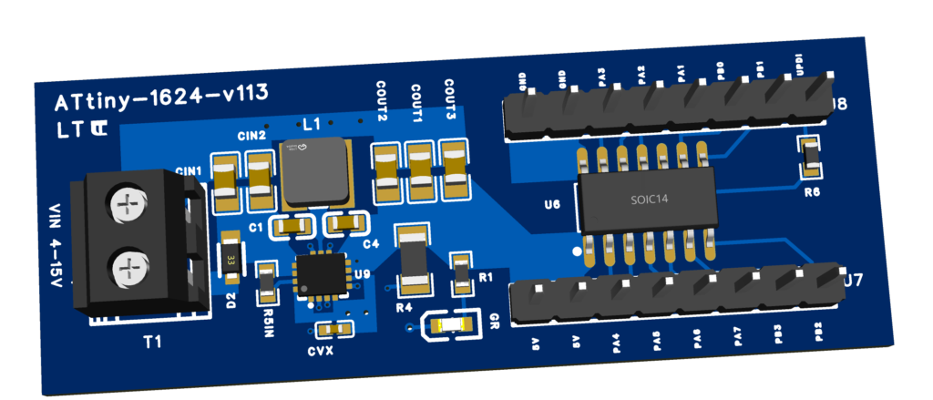
This custom dev board is built around the ATtiny1624 microcontroller. It includes onboard power regulation and is UPDI-programmable via an Arduino Nano or similar.
⚙️ Key Specs
✅ Microcontroller: ATtiny1624
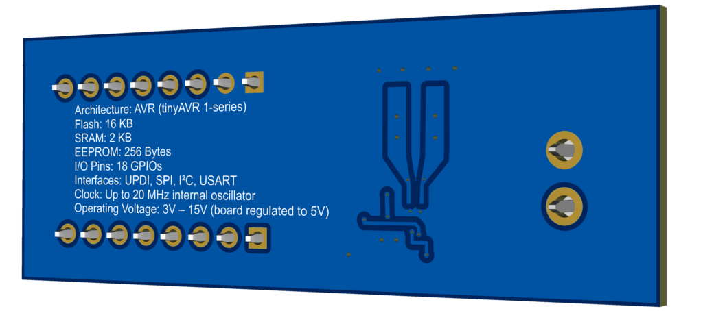
Architecture: AVR (tinyAVR 1-series)
Flash: 16 KB
SRAM: 2 KB
EEPROM: 256 Bytes
I/O Pins: 18 GPIOs
Interfaces: UPDI, SPI, I²C, USART
Clock: Up to 20 MHz internal oscillator
Operating Voltage: 1.8V – 5.5V (board regulated to 5V)
🔌 Power Supply
Input Voltage (VIN): 3V to 15V via terminal block labeled
VIN 4–15VRegulator IC:
Buck-boost converter
Regulates input to stable 5V
Protection Diode: for reverse polarity protection
🔄 Programming Interface: UPDI
Pin PA0 on ATtiny1624 serves as the UPDI programming pin.
🛠️ Programming with Arduino Nano (as UPDI programmer)
You can use an Arduino Nano to program the ATtiny1624 via UPDI using the following method:
✅ Required:
Arduino Nano
PyUPDI script or megaTinyCore in Arduino IDE
🔌 Wiring
| Nano Pin | ATtiny1624 Board Pin | Notes |
|---|---|---|
| D6 | PA0 (UPDI) | Via 4.7kΩ resistor (on Board) |
| GND | GND | Common ground |
| 5V | VDD (5V rail) | Optional (if not powered) |
💻 Programming Steps
Install megaTinyCore in Arduino IDE.
Select:
Board: ATtiny1624/1626/1627
Programmer: jtag2updi (megaTinyCore)
Burn bootloader (to set fuses).
Upload sketches via UPDI.
🔌 I/O Headers
There are two 8-pin headers:
U7(bottom side): PA4–PA7, PB2–PB3, and power pins (5V, GND)U8(top side): PA0–PA3, PB0–PB1, PA0 doubles as UPDI