Skip to content

ATtiny 84 Dev Board

🧾 ATtiny84 Dev Board (GTMSM V0.1) – Specs & Programming Guide


1. 🔋 Power Supply

  • VIN input range: 3V to 15V (recommended)

  • Recommended VIN for operation: 3V or higher

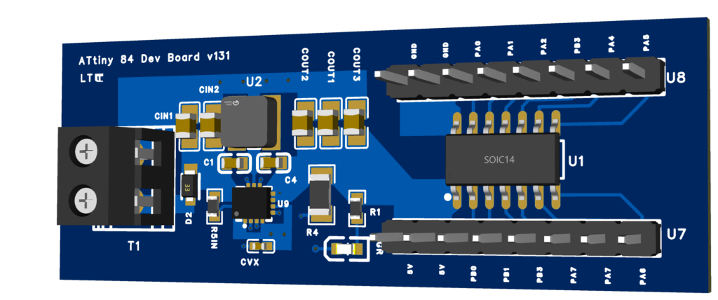
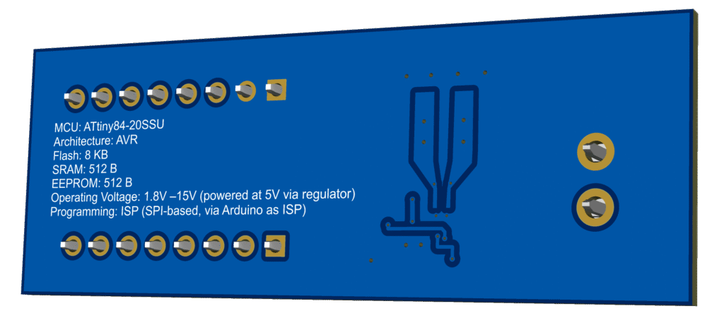
  • Regulated output: 5V (via onboard buck-boost converter)

  • Minimum reliable VIN (with diode drop): ~2.8V

  • Reverse voltage protection: Schottky diode (PD3S140-7) on VIN input

  • ⚠️ Important: Never power the board from more than one source at a time (e.g. VIN and USB simultaneously)


2. 🧠 Microcontroller

  • Chip: ATtiny84-20SSU

  • Architecture: AVR

  • Flash memory: 8 KB

  • SRAM: 512 bytes

  • EEPROM: 512 bytes

  • Operating voltage: 1.8V – 5.5V

  • Clock: Internal up to 8 MHz (configurable via fuses)


3. 🔌 I/O & Pinout

  • Two 8-pin headers:

    • One header: PA0 to PA5, GND

    • Other header: PB0 to PB3, PA6, PA7, 5V, GND

  • Standard GPIO, ADC, SPI, I²C, UART functionality via these pins


4. 🛠️ Programming (Using Arduino Nano as ISP)

🧰 Requirements:

  • Arduino Nano

  • Jumper wires

  • Arduino IDE with ATtinyCore installed

  •  

🔗 Wiring: Arduino Nano → ATtiny84

Arduino NanoATtiny84 PinFunction
D13PA4SCK
D12PA5MISO
D11PA6MOSI
D10PA3RESET
5VVCCPower
GNDGNDGround

5. 🧪 Programming Steps

  1. Flash the Arduino Nano with the “ArduinoISP” sketch

  2. In Arduino IDE:

    • Board: ATtiny84 (No bootloader / ATtinyCore)

    • Programmer: Arduino as ISP

    • Clock: 8 MHz internal (or your choice)

  3. Click “Burn Bootloader” to set fuses

  4. Use “Upload Using Programmer” to flash your sketch