Overview #
The GTVCUCR is a comprehensive monitoring and control unit designed for efficient battery management and system safety.
It monitors critical parameters like battery health, temperature, humidity, and state of charge (SoC), providing real-time insights and diagnostics.
The unit can control cooling systems by activating fans or other equipment through a relay board and is equipped to shut down the system in case of excessive temperatures, ensuring safety.
With capabilities like battery health estimation and temperature monitoring for various components, the GTVCUCR is essential for optimizing performance and maintaining system reliability.
- Bluetooth Connectivity: Integration with an Android app for remote monitoring and control.
- Power Input: Supports 8-30 VDC power input for versatile installation options with reverse polarity protection.
- Temperature and Humidity Sensors: Includes Temperature and Humidity sensor for accurate environmental monitoring.
- Equipment Temperature Monitoring: Three dedicated sensors for precise equipment temperature tracking.
- Battery Voltage Level Input: Monitors battery status for reliable operation. Supports 12V and 24 VDC Battery inputs with reverse polarity protection.
- Battery Current Level Input: Monitors battery Charge/Discharge status and SoC level.
- Relay Board Output Port: Provides a versatile interface for controlling external devices.
- LED Operation Indicators: Visual indicators for operational status and diagnostics.
- Updates: Firmware Updates through GTVcarMon App.
⚠️ WARNING #
The RELAY and GTVCUCR boards are designed strictly for DC use only.
DO NOT USE WITH AC MAINS POWER
Using the relay or the GTVCUCR boards with AC power can result in malfunction, severe damage to the equipment, and potential safety hazards, including fire or electric shock.
Always ensure the connected power source is DC and within the specified voltage and current ratings for the RELAY and GTVCUCR boards.
Misuse may void the warranty and pose serious risks.
Follow all safety guidelines and installation instructions provided in this document.

Voltage Input 8V – 30V DC
Power Consumption 70mA max (30mA idle state)
TH Sensor Temperature Range 0 – 100C°
Ambient Temp/Hum Sensor Range 0 – 100C° / 0 – 100%
Current Sensor Range 10A – 200A
Relay Board Connector Can control up to 4 Relays
Factory reset Button Reset Device to factory settings
Operating Temperature -20C° – 80C°
IP Rating IP 4
Vin Connector Terminal size Up to 2.5mm² / AWG 14 / Swg 13
Power Supply and Terminal Connection Guidelines
Input Voltage (Vin):
Ensure the input voltage is within the range of 8V DC to 30V DC.
Fuse Requirement:
A 3A fuse must be connected to the Vin terminal for circuit protection. A switch is recommended.
Terminal Description:
The Temperature and Humidity (Temp. Hum.) terminal is identical to the Current Sense terminal. Verify that the correct peripheral is connected to the appropriate terminal.
Temperature Sensor Terminals (TH1-TH3):
These terminals are designed for temperature sensors.
The connections are non-polarized, meaning you can connect the sensor in either direction.
Relay Board Connection:
The Relay Board terminal is used to connect to the relay board via the supplied cable. Ensure a secure and proper connection.
Powering the GTVCUCR for the First Time #
The GTVCUCR is shipped in Factory Mode, ready for initial setup.
When powered on for the first time, a rapid blinking pattern (20 blinks/second) of the green LED indicates that the device is unpaired with the phone app.
To proceed, you must enter Pairing Mode to connect and update the device. Follow these steps:
Press and hold the Factory Reset button until the green LED stays lit.
Release the button. The GTVCUCR will now enter Pairing Mode.
In Pairing Mode, the green LED will display the following pattern: Two short blinks, followed by staying ON for 2 seconds. Two short blinks, followed by staying OFF for 2 seconds.
At this stage, the GTVCUCR is ready for new connections.
Factory Reset Button #

Resetting the GTVCUCR to factory mode (Hard Reset). #
If the GTVCUCR has a firmware installed and you wish to reset it to factory settings, perform the following steps:
Press and hold the Factory Reset button until the green LED stays lit, indicating the unit has entered Factory Reset Mode.
Release the button. The device will reset to factory settings.
After resetting: The green LED will blink every second, 10 times to indicate the completion of the reset. The device will then reboot and return to Factory Mode.
This process is a Hard Factory Reset, which erases both stored data and the firmware. If you want to reset only the stored data while keeping the firmware intact, you can perform a Soft Factory Reset via the App.
GTVCUCR Firmware Update #
The firmware update process is simple and user-friendly.
Follow these steps to ensure a successful update:
Connect to the GTVCUCR via the App:
Automatic Update Check:
Once connected, the app will automatically check for available updates. If an update is available, the Update button will appear.
Navigate to the Update Page:
Tap the Update button to proceed to the GTVCUCR firmware update page.
Download the Firmware:
On the update page, the Download button will be enabled. Tap the Download button to start downloading the latest GTVCUCR firmware. The app will handle everything automatically:
It will download the firmware.
Validate the downloaded file.
Once the download is complete and validated, the Download button will be disabled, and the Upload button will be enabled.
Upload the Firmware:
Tap the Upload button to begin uploading the new firmware to your GTVCUCR unit.
Stay close to the unit during this process and avoid navigating away from the app.
Handling Interruptions:
If you receive a call during the upload, the app will pause the upload and resume it automatically once the call is ended and you return to the upload page.
Completion and Verification:
Wait for the firmware to be fully uploaded and verified. Once the process is complete, a confirmation message will appear, prompting you to return to the Main Page.
Installation and Protection Guidelines for the GTVCUCR Unit #

Preferred Installation Position:
Install the GTCUCR unit in the upright position, as shown in the illustration above.
Ensure the unit is securely mounted to avoid movement or vibrations during operation.
Ventilation Requirements:
Place the unit in a well-ventilated area to maintain proper airflow and prevent overheating. For optimal performance, it is recommended to install the unit in a fan-ventilated compartment.
Protection from Heat:
Keep the GTCUCR unit away from heat sources, such as engines or other heat-generating equipment. Avoid installing the unit in engine compartments or locations exposed to high temperatures.
Environmental Considerations:
Ensure the unit is protected from water splashes, dust, and other contaminants to prevent terminal clogging or damage. Install the unit in a location that is dust-free and shielded from direct sunlight to avoid potential damage from UV exposure. Avoid areas prone to high humidity or water ingress.
Maintenance and Accessibility:
Mount the unit in a location that is easily accessible for maintenance and troubleshooting. Ensure there is sufficient clearance around the unit for cable connections and ventilation.
Shock and Vibration Protection:
Use proper mounting techniques and brackets to minimize the effects of shock and vibration. Avoid installing the unit in areas subject to significant mechanical stress.
Cable Management:
Use appropriate cable sleeves or conduits to protect wires and ensure they are securely fastened to avoid accidental disconnections. Keep cables organized and routed away from moving parts or sharp edges.
General Safety:
Do not expose the unit to corrosive chemicals or gases. Regularly inspect the unit and its surroundings to ensure continued protection and performance. By following these guidelines, you can maximize the lifespan and performance of your GTCUCR unit while ensuring safe and reliable operation.
Current Sensor Installation #


The image depicts the proper setup for connecting the TH1 temperature sensor and the current sensor to the battery.
Here’s a detailed description of the connection requirements:
TH1 Temperature Sensor Placement:
The TH1 temperature sensor should be securely connected to the battery terminal to measure the battery’s temperature accurately.
Current Sensor Connection:
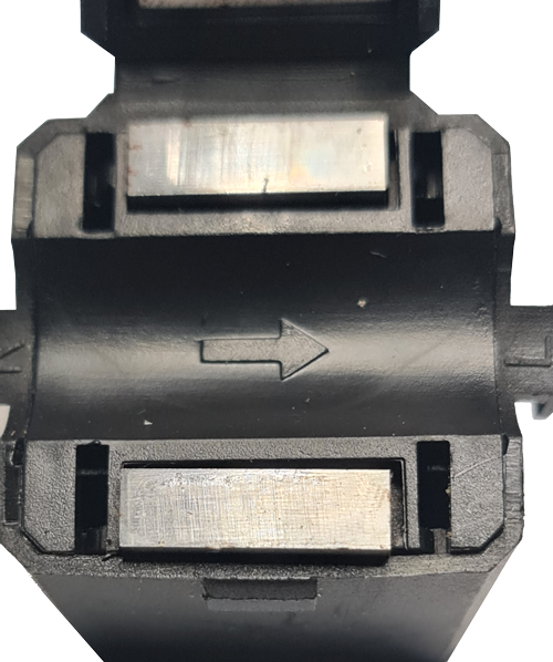
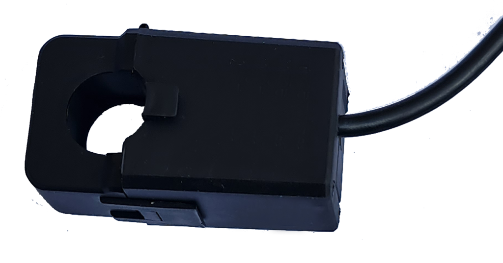
The current sensor must be placed on the negative cable of the battery. Ensure that: The arrow inside the split loop of the current sensor is pointing outward, away from the battery, to correctly measure the current direction.
Close the current sensor securely.
Negative Cable Configuration:
No other cables should connect directly to the negative terminal of the battery before the current sensor. All additional connections (if any) to the negative terminal must be made after the current sensor.
During Calibration:
Ensure the current sensor is closed and securely placed on the battery.
This setup ensures proper alignment for accurate current measurement and effective temperature compensation.
Current Sensor Calibration #
Procedure to Calibrate the Current Sensor
Note:
Calibrate always before installation to ensure accurate readings.
Re-calibrate whenever you change the sensor (e.g., switching from a 100A sensor to a 200A sensor).
Perform calibration before the first use of the system.
Calibration Steps:
Prepare the System:
Power on the GTVCUCR unit and ensure it is connected to the app via Bluetooth. Place the current sensor away from any cables or conductive materials to avoid interference.
TH1 Temperature Sensor :
It is important to have this sensor installed prior to current sensor calibration as temperature compensation is used for correct current sensor calibration and current measurement.
Open the App:
Navigate to the Battery Settings page in the app.
Method 1:
More accurate calibration
Leave the current sensor clamped on the battery.
Disconnect or switch off all loads (ensure no load is connected to the battery).
Perform sensor calibration.
This process accounts for any interference from the battery’s negative cable.
Method 2:
Remove Sensor Connections:
Disconnect the current sensor from the battery cable. ..
Place the sensor on the battery, ensuring it’s away from metal brackets or the car chassis to prevent interference, and close the split core.

Initiate Calibration:
Click the Calibrate Sensor button in the app.
Observe the Process:
During calibration, the LED indicator on the unit will stay lit to indicate the process. The app will display test progress in real time.
Calibration Complete:
Once calibration is complete, the results will be stored in the GTVCUCR memory for future use.
Verify Calibration:
Do not clamp the sensor to the battery as yet.
Observe the readings on the app.
Ensure the readings stabilize around 0A (typically +- .03A)
when no current is flowing. Repeat the calibration if the reading exceeds +-.03A, ensuring the sensor is away from metal brackets or the car chassis to prevent interference, and it is properly closed.
Final Checks:
Connect the sensor back on the battery and ensure all cables are reconnected securely.
Test the system under normal operational conditions to confirm proper functionality.
Avoid performing calibration near large electrical equipment that generates strong EMFs.
If the calibration fails, ensure all connections are correct and repeat the process.
LED Indicators on GTVCUCR board #

| LED blink pattern | Indication |
| Infinite rapid blinking at a rate of 20 times per second | This indicates that the GTVCUCR is unpaired with the phone app. This behavior occurs in Factory Mode or when the device has active firmware, but awaiting app pairing. |
| Two short blinks followed by staying ON for 2 seconds, then two short blinks followed by staying OFF for 2 seconds | This indicates that the GTVCUCR is in Factory Mode and is actively waiting for connections. |
| One short blink every second | This indicates that the GTVCUCR is running in firmware mode. |
| Ten blinks one blink every second | This Indicates the completion of the factory reset. |
| The LED will stay lit | The GTVCUCR performs a current sensor calibration |
| Blue LED: | The Blue LED remains lit to indicate that the device is powered on. |