
1. Overview
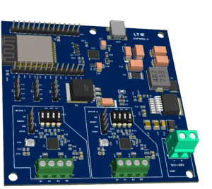
The ESP32 Ethernet DC Development Board is a robust wired-Ethernet ESP32 platform designed for industrial, automation, and embedded control applications.
It combines an ESP32-D0WD-V3 (rev 3.1, 16 MB flash) with a LAN8720A Ethernet PHY, wide-range 8–60 V DC input, onboard switching regulation, and USB-C programming.
This board is intended for permanently powered, network-connected devices where reliability, clear pin ownership, and wide supply tolerance are required.
⚠️ This board does NOT support Power over Ethernet (PoE).
Ethernet is data only.
2. Key Features
ESP32-D0WD-V3 (revision 3.1)
Dual-core Xtensa LX6
Up to 240 MHz
Wi-Fi + Bluetooth (optional use)
16 MB external flash
Wired Ethernet
LAN8720A PHY
10/100 Mbps
RMII interface
RJ45 with integrated magnetics
Link / activity LEDs
Wide Input Power
VIN: 8–60 V DC
High-efficiency buck regulator
Onboard 5 V and 3.3 V rails
Suitable for industrial and automotive environments
USB-C Interface
Firmware upload
Serial debug console
Auto-reset / auto-boot circuitry
USB power diode-ORed with external supply
Clearly Broken-Out I/O
ESP32 GPIO headers
Power rails on headers
Reset and BOOT access
3. Power Architecture
Power Inputs
VIN (8–60 V DC) via screw terminal
USB-C 5 V (programming / light operation)
Power Path Behavior
USB 5 V is diode-isolated from the main board supply
External VIN and USB may be connected simultaneously
The higher voltage source automatically powers the board
No back-feeding into the USB port
Power Rails
Buck regulator generates 5 V
LDO generates 3.3 V for ESP32 and Ethernet PHY
⚠️ Ethernet does not provide power (no PoE)
4. Programming & Operation
Firmware Upload
Firmware is uploaded via USB-C
USB provides:
Programming
Serial monitoring
Ethernet is not used for flashing
Important Notes
Disconnect external loads during firmware upload if the board is powered only from USB
USB may not supply enough current for all peripherals
Board is designed for continuous powered operation from VIN
5. Ethernet Interface (LAN8720A)
Hardware Configuration
Ethernet PHY is hard-wired to the ESP32 using RMII
GPIO assignments are fixed in hardware
Pins cannot be remapped
Software Requirement
Ethernet must be enabled in firmware
The firmware must reference the predefined GPIO pins
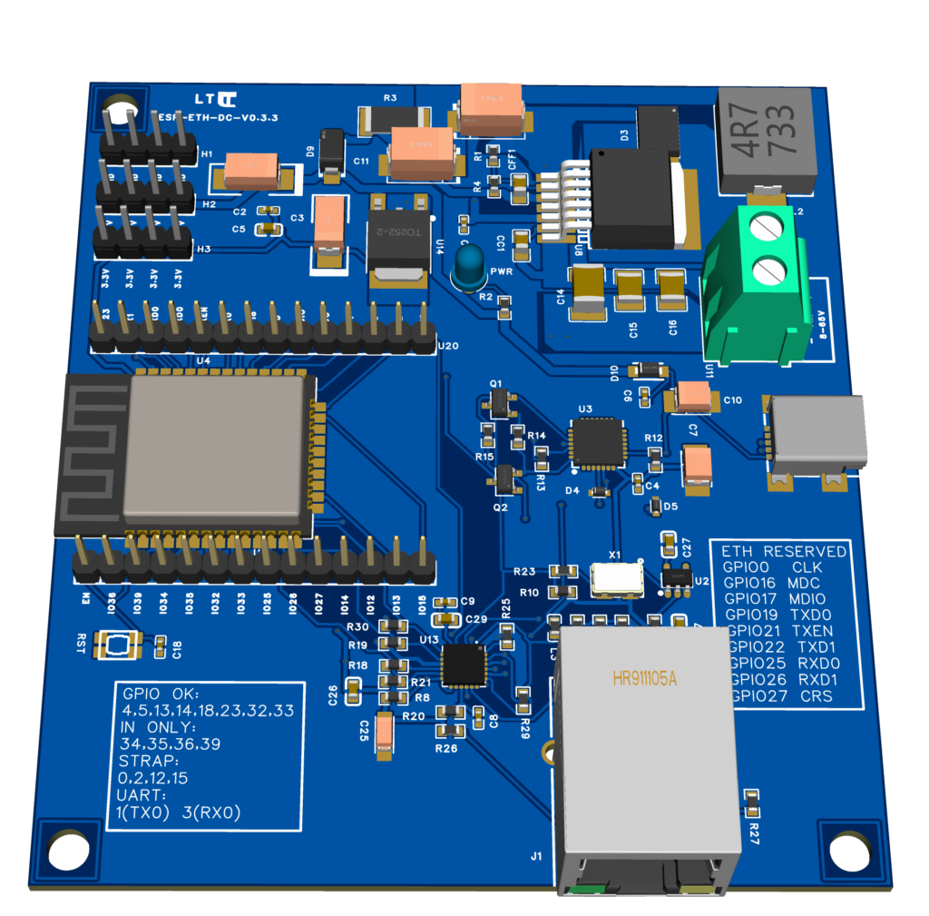
6. Ethernet Pin Mapping (Fixed)
⚠️ RESERVED – DO NOT USE AS GPIO
These pins are permanently assigned to Ethernet and are not available for general I/O:
| Function | ESP32 GPIO |
|---|---|
| RMII Clock | GPIO0 |
| MDC | GPIO16 |
| MDIO | GPIO17 |
| TXD0 | GPIO19 |
| TXEN | GPIO21 |
| TXD1 | GPIO22 |
| RXD0 | GPIO25 |
| RXD1 | GPIO26 |
| CRS_DV | GPIO27 |
7. ESP32 GPIO Availability
General-Purpose GPIO (Available)
GPIO1   TX0 (UART0 TX)
GPIO3   RX0 (UART0 RX)
GPIO4
GPIO5
GPIO13
GPIO14
GPIO18
GPIO23
GPIO32
GPIO33
GPIO1 and GPIO3 are used by USB serial but may be repurposed if UART0 is not required.
Input-Only GPIO
GPIO34  INPUT ONLY
GPIO35  INPUT ONLY
GPIO36  INPUT ONLY
GPIO39  INPUT ONLY
Notes:
No output capability
No internal pull-ups/downs
Ideal for sensors and analog inputs
Boot / Strapping Pins (Use with Care)
GPIO0
GPIO2
GPIO12
GPIO15
These pins affect boot behavior and must not be driven incorrectly during reset.
8. Safety & Usage Notes
No PoE support — data only
Do not drive Ethernet GPIOs
Do not overload USB power
Ensure proper grounding for industrial environments
Use regulated VIN supply
9. Typical Applications
Industrial controllers
Automation gateways
Ethernet-connected sensors
Remote monitoring devices
Networked power and control systems
DIN-rail mounted controllers
10. Summary
This board is designed for real-world deployment, not just prototyping:
Wide VIN range
Proper Ethernet implementation
Clear pin ownership
Safe power OR-ing
Long-term stable operation
It provides a solid foundation for wired ESP32 systems where reliability and clarity matter.